Configuration → Ports or click on the port status LEDs in the status bar.
You can choose the port to configure either by clicking on the LED in the status bar, or by incrementing/decrementing the port number with the arrow buttons next to the title. Additionally you can use the cursor left/cursor right keys.
If you have actived user labels, the title shows not only the port number, but also the input and output port names you have given, as seen above.

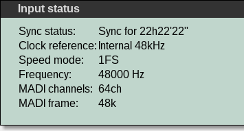
On the top of each port's configuration page, you can see details about the port input signal:

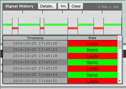
On the right side the input signal history since power up is shown graphically. Black indicates no signal, red a signal lock and green stands for sync. This graph gives you an idea of the signal quality and helps you narrow down setup problems.
Every vertical line stands for one status change event. The color bars have a minimum width to enhance visibility, so if there are many events in a short period, they might form a continuous bar.

If you need the raw data for debugging purposes, click on the "Details.." button above the graph. A popup table shows you a table with the raw data of all signal status events. To hide the table, press "Details.." again.
Note: Up to 1024 events are stored. To clear the history for the current port, press the Clear button.
The input and output of each port always use the same clock reference and speed mode. It is not possible to change them individually. The clock reference is used to check the incoming signal against for synchronicity, and it is the clock source for the outgoing MADI stream.

If Follow Port is active, the clock configuration elements are disabled and clock reference as well as speed mode are copied from the respective port. This way you can easily create clock domains where multiple ports are guaranteed to always use the same clock setting, and you can configure them with one click. You can see the current settings in the input status section or on the configuration page for the clock source you have chosen to follow.
If Master clock override or Master FS override are in effect, the corresponding configuration elements are disabled. You can see the current settings in the input status section or on the word clock configuration page.

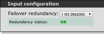
The M.1k2 allows you to define any two MADI inputs to be redundant to each other. In case one of the incoming signals fails, the signal of the still working port is used instead.
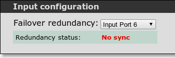
The current status of your input redundancy is always visible on each port's configuration pages and in the status bar:

If the incoming signals differ in clock or MADI mode/frame, the indicators turn yellow and give you a description of the condition. In case of an error, they turn red:


The output configuration section allows you to set the properties of the outgoing MADI signal:
To manually enable 57 channel mode, chose "57ch" in the Output Configuration section of the port in question. Note: This option is only selectable if automatic 57 channel switching is deactivated.
The channel routing panel lets you inspect all the destinations for the incoming channels and the sources for the outgoing channels at once. Locked channels are displayed dimmed, while connections with (probably) asynchronous ports are hilighted in red. Examples:
A single route in the input channel section. This input channel is routed to port 1, channel 28. In the output channel section this would indicate that the source for this output channel is port 1, channel 28.
No routes for this input/output channel active.

This input channel is routed to multiple output channels, channel 1 on ports 1—3.
The cycle box on the upper right lets you switch between system labels and user provided labels for the channels and ports. A click on the cycle box switches or pressing ![]() cycles through the settings.
cycles through the settings.
The active routing and clock reference assignment can be exported using the "Export Routing" button. This creates a CSV file that lists all input channels and their destination channels.
For every input channel, the following information is exported:
For every output of an input channel, the following information is exported:
These 6 columns are repeated for every output channel in one single row.